- Voltage up to 1,200 V
- 800 V isolation voltage between negative losd input and PE at galvanically isolated I/O port
- Current up to 2,700 A
- Power 600 W ... 28,800 W
- Temporary power overload capacity, depending on model
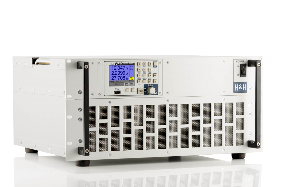
- High power density up to 2,100 W in 2 HU (3,200 W in 3 HU)
- Ethernet + USB + RS-232 + CAN as standard (GPIB optional)
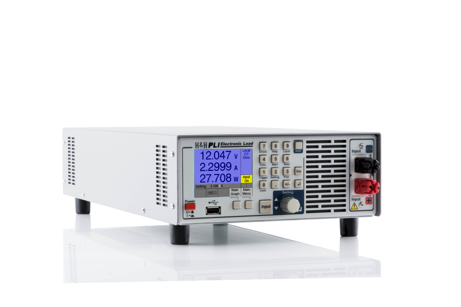
- Intuitive operation
- Quick operation by shortcuts
- Current, voltage, resistance and power mode
- MPPT Function
- Energy storage test
- Internal resistance measurement combineable with dynamic function
- Protections for current and voltage
- Dynamic loads
- SCPI programming with measurement function
- USB flash drive as measurement data memory
- Electronic protection
- Analog measurement outputs for voltage and current
- Analog control input
- Digital input and programmable control output
- Silent fan cooling
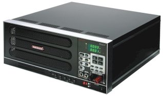
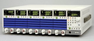
PLI Series
Description
The PLI series of electronic loads provide a comfortable operation by a graphical user interface. The PLI series highlight is the extensive variety of standard interfaces. Apart from Ethernet, USB, RS-232 and Analog interface there is a standard CAN interface. Programming is done in SCPI syntax.
Functions
The units provide constant current mode, constant voltage mode, constant power mode and constant resistance mode.
In addition, protections for current and voltage can be set in any mode.
A static data acquisition function allows to store measurement data on an external USB flash drive.
Dynamic operation can be configured by up to 300 list point settings. The Electronic Load saves the synchronously acquired measurement data with timestamp.
A configurable trigger model controls data acquisition, static and dynamic settings.
Special Functions
Energy Storage Test/Discharge Function
An implemented test function enables discharging energy storages such as accumulators, batteries, ultracaps etc. in an easy way and supplying determined values like charge and energy.
Internal Resistance Measurement
Measurement of the internal DC resistance of energy storage systems such as batteries, accumulators, capacitors, as well as cables, power supplies and so on.
Watchdog Function
When the watchdog function is activated, the load input is switched off in the event of a faulty communication with the control PC in order to protect the connected test item.
MPP Tracking (Optional)
The Electronic Load automatically searches for the Maximum Power Point of solar panels and self-adjusts as the sun's radiation changes.
Loading capacity
The model range covers power classes from 600 W, up to 28,000 W continuous power rating.In addition the models up to 300 V have an overload capability. The height and duration of the possible overload depends on the temperature of the power stage. The unit indicates the currently possible overload. Therefore the units can be used even for considerably more powerful applications.
Protections
• Current limitation
• Power limitation
• Overtemperature protection
• Undervoltage indicator
• Protection of the GND lines at the Analog I/O Port
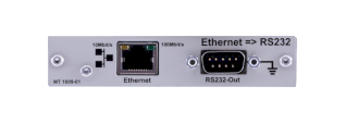
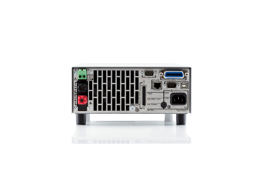
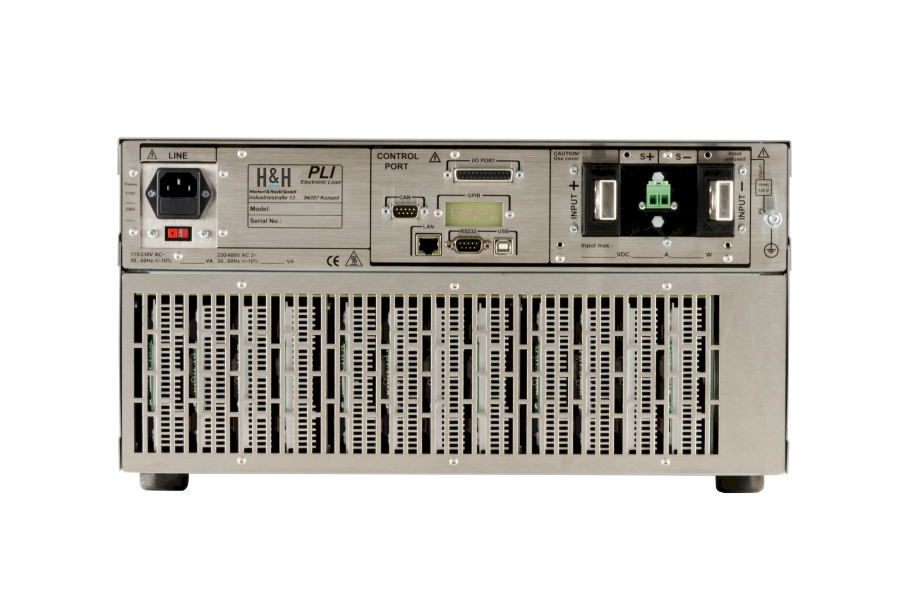
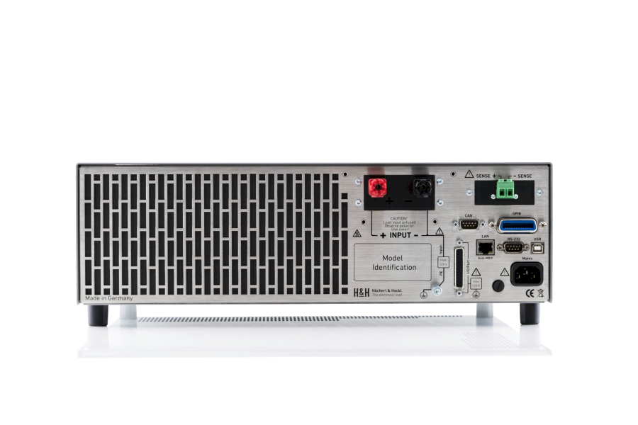
Data Interfaces
The following interfaces are included as standard:
• Ethernet
• USB
• RS-232
• CAN
LabVIEW drivers are certified by National Instruments.
Analog I/O Port
The standard Analog I/O Port provides the following functions:
• Load setting C and V
• Analog setting the C and V protections
• Load on-off
• Voltage monitor output
• Current monitor output
• Trigger input
• Trigger output
• Programmable digital input and control output
Galvanically isolated Analog I/O Port
For the galvanic isolation between the Analog I/O Port and the load terminals the PLI06 option can be installed. Isolation voltage is 800 V.
Using this board also prevents ground loops.
Factory Calibration Certificate
A free Factory Calibration Certificate (FCC) is supplied with the devices. The FCC meets the requirements according to DIN EN ISO 9000ff. This calibration certificate documents the traceability to national standards to illustrate the physical device in accordance with the international System of Units (SI). Within the warranty period we calibrate a second time for free.
--> Conditions for a second free calibration
The recommended calibration interval is 2 years.
Documentation
We supply a User Manual as pdf file and printed General Safety Instructions, each in German and English.
-
Pdf
PLI7030EC-datasheet.pdf
(Pdf, 521.99 KB) -
Pdf
PLI4260-datasheet.pdf
(Pdf, 349.2 KB) -
Pdf
PLI4230-datasheet.pdf
(Pdf, 349.21 KB) -
Pdf
PLI3280-datasheet.pdf
(Pdf, 349.19 KB) -
Pdf
PLI9880-datasheet.pdf
(Pdf, 687.9 KB) -
Pdf
PLI9860EC-datasheet.pdf
(Pdf, 687.91 KB) -
Pdf
PLI9830-datasheet.pdf
(Pdf, 687.91 KB) -
Pdf
PLI8480-datasheet.pdf
(Pdf, 521.99 KB) -
Pdf
PLI8460EC-datasheet.pdf
(Pdf, 522 KB) -
Pdf
PLI8460-datasheet.pdf
(Pdf, 522 KB) -
Pdf
PLI8012-datasheet.pdf
(Pdf, 522 KB) -
Pdf
PLI7060EC-datasheet.pdf
(Pdf, 521.99 KB) -
Pdf
PLI7060-datasheet.pdf
(Pdf, 521.98 KB) -
Pdf
PLI4260EC-datasheet.pdf
(Pdf, 349.21 KB) -
Pdf
PLI16012-datasheet.pdf
(Pdf, 687.91 KB) -
Pdf
PLI14412-datasheet.pdf
(Pdf, 687.92 KB) -
Pdf
PLI14406-datasheet.pdf
(Pdf, 687.92 KB) -
Pdf
PLI14060-datasheet.pdf
(Pdf, 687.9 KB) -
Pdf
PLI14030EC-datasheet.pdf
(Pdf, 687.91 KB) -
Pdf
PLI14030-datasheet.pdf
(Pdf, 687.9 KB) -
Pdf
PLI12812-datasheet.pdf
(Pdf, 687.91 KB) -
Pdf
PLI12630-datasheet.pdf
(Pdf, 687.92 KB) -
Pdf
PLI11280-datasheet.pdf
(Pdf, 687.91 KB) -
Pdf
PLI11260EC-datasheet.pdf
(Pdf, 687.9 KB) -
Pdf
PLI11260-datasheet.pdf
(Pdf, 687.9 KB) -
Pdf
PLI2180-datasheet.pdf
(Pdf, 172.83 KB) -
Pdf
PLI1406C20-datasheet.pdf
(Pdf, 177.05 KB) -
Pdf
PLI660-datasheet.pdf
(Pdf, 177.04 KB) -
Pdf
PLI630-datasheet.pdf
(Pdf, 177.05 KB) -
Pdf
PLI612-datasheet.pdf
(Pdf, 172.84 KB) -
Pdf
PLI606-datasheet.pdf
(Pdf, 177.07 KB) -
Pdf
PLI606C10-datasheet.pdf
(Pdf, 172.83 KB) -
Pdf
PLI144K12HV-datasheet.pdf
(Pdf, 176.88 KB) -
Pdf
PLI3260-datasheet.pdf
(Pdf, 176.86 KB) -
Pdf
PLI3230EC-datasheet.pdf
(Pdf, 176.87 KB) -
Pdf
PLI3212-datasheet.pdf
(Pdf, 176.87 KB) -
Pdf
PLI3206-datasheet.pdf
(Pdf, 176.87 KB) -
Pdf
PLI1460-datasheet.pdf
(Pdf, 172.82 KB) -
Pdf
PLI2160-datasheet.pdf
(Pdf, 172.83 KB) -
Pdf
PLI2130-datasheet.pdf
(Pdf, 172.84 KB) -
Pdf
PLI2112-datasheet.pdf
(Pdf, 172.83 KB) -
Pdf
PLI2106-datasheet.pdf
(Pdf, 172.84 KB) -
Pdf
PLI1480-datasheet.pdf
(Pdf, 172.82 KB) -
Pdf
PLI6412-datasheet.pdf
(Pdf, 522 KB) -
Pdf
PLI6406-datasheet.pdf
(Pdf, 522 KB) -
Pdf
PLI5680-datasheet.pdf
(Pdf, 522 KB) -
Pdf
PLI5660-datasheet.pdf
(Pdf, 521.99 KB) -
Pdf
PLI5630-datasheet.pdf
(Pdf, 522 KB) -
Pdf
PLI4806-datasheet.pdf
(Pdf, 349.21 KB)