• I/O Port as standard
• Optional Ethernet + USB + RS-232
• Optional CAN Interface
• Optional GPIB Interface (not at PLA2xx)
• CC - CV - CR - CP Mode
• Protections for current and voltage
• MPP tracking
• V/I characteristic curves
• Digital Master-Slave operation
• Watchdog at remote control
• SCPI programming with DAQ function
• Dynamic loads
• Depending on model, temporary overload capacity
• Electronic protection
• Silent fan cooling
• 19 inch installation possible
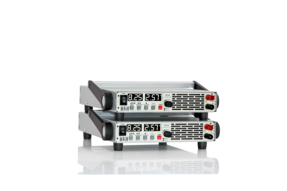
PLA Series
Description
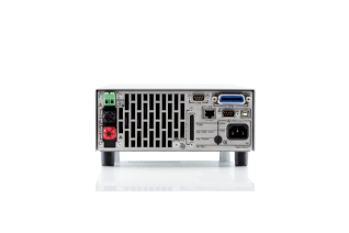
PLA series electronic loads combine classic design, large display with modern interfaces and great functionality. The highlight of the PLI series is the extensive variety of optional interfaces. In addition to Ethernet, USB, RS-232 can be installed and also a CAN interface. In addition, for devices with 400 W GPIB is optionally available. I/O port ist standard. Programming is done in SCPI syntax.
Functions
The units provide constant current, constant voltage, constant resistance and constant power mode. In addition, protections for current and voltage can be set in any mode. Dynamic operation can be configured by up to 100 list point settings. A data acquisition function allows to save 100 measurement points (time, voltage, current) on an internal memory chip.
Special Functions
V/I Characteristic Function
In the V/I characteristic function, a sequence of voltage values is interpolated linearly to a sequence of current values (2 to 100 values each). Depending on the value of the input voltage, the electronic load sets the current which corresponds to the interpolated point of the characteristic. In this way non-linear characteristics such as diode characteristics can be simulated.
Maximum Power Point Tracking (MPPT)
An extensive Maximum Power Point Tracking (MPPT) function for testing photovoltaic panels can be activated. In variable sweep periods, the V/I characteristic of the panel is measured and stored. The sweep direction is selectable. The absolute maximum power found is controlled until the function is stopped or a certain minimum voltage is underrun. If the panel voltage is above the minimum voltage again, the load continues the sweep and control process.
Digital Master-Slave Operation
To increase the power or current capability up to 5 electronic loads of equal type can be operated in parallel in Master-Slave mode as one system.
The Master unit controls the total input current of the system. This unit also shows the system’s total measurement values at its display and returns them in case of query via one of the data interfaces. The voltage measured at the Master unit is the base for the controlled settings in voltage mode, power mode and resistance mode.
Watchdog
When controlled via a data interface, a watchdog can be activated to protect the load input and thus the DUT, which switches off the load input if the communication interface fails or malfunctions.
Loading Capacity
The type spectrum contains models in the power categories 200 W, 400 W, 800 W and 1200 W. In addition, the models up to 300 V have an overload capability. The level and duration of the possible overload depends on the temperature of the power stage. Therefore the units can be used even for considerably more powerful applications for a short time.
Protections
• Current limitation
• Power limitation
• Overtemperature protection
• Overvoltage indicator
• Undervoltage indicator
• Protection of the GND lines at the I/O Port
Tools
The delivery includes comfortable tools for PC control.
I/O Port
The standard I/O Port provides the following functions:
• Load setting C and V
• Load on/off
• Voltage monitor output
• Current monitor output
Factory Calibration Certificate
A free Factory Calibration Certificate (FCC) is supplied with the devices. The FCC meets the requirements according to DIN EN ISO 9000ff. This calibration certificate documents the traceability to national standards to illustrate the physical device in accordance with the international System of Units (SI). Within the warranty period we calibrate a second time for free.
--> Conditions for a second free calibration
The recommended calibration interval is 2 years.
Documentation
We supply a user manual as pdf file and printed General Safety Instructions, each in German and English.
-
Pdf
PLA480-datasheet.pdf
(Pdf, 149.49 KB) -
Pdf
PLA412-datasheet.pdf
(Pdf, 149.5 KB) -
Pdf
PLA812-datasheet.pdf
(Pdf, 165.71 KB) -
Pdf
PLA206C4-datasheet.pdf
(Pdf, 145.11 KB) -
Pdf
PLA206-datasheet.pdf
(Pdf, 145.12 KB) -
Pdf
PLA212-datasheet.pdf
(Pdf, 145.12 KB) -
Pdf
PLA212C2-datasheet.pdf
(Pdf, 145.11 KB) -
Pdf
PLA230-datasheet.pdf
(Pdf, 145.1 KB) -
Pdf
PLA280-datasheet.pdf
(Pdf, 145.1 KB) -
Pdf
PLA406C8-datasheet.pdf
(Pdf, 149.5 KB) -
Pdf
PLA406-datasheet.pdf
(Pdf, 149.5 KB) -
Pdf
PLA412C4-datasheet.pdf
(Pdf, 149.5 KB) -
Pdf
PLA430-datasheet.pdf
(Pdf, 149.49 KB) -
Pdf
PLA1280-datasheet.pdf
(Pdf, 165.71 KB) -
Pdf
PLA806C16-datasheet.pdf
(Pdf, 165.71 KB) -
Pdf
PLA806-datasheet.pdf
(Pdf, 161.7 KB) -
Pdf
PLA812C8-datasheet.pdf
(Pdf, 165.7 KB) -
Pdf
PLA830-datasheet.pdf
(Pdf, 165.7 KB) -
Pdf
PLA880-datasheet.pdf
(Pdf, 165.69 KB) -
Pdf
PLA1206C24-datasheet.pdf
(Pdf, 161.7 KB) -
Pdf
PLA1206-datasheet.pdf
(Pdf, 165.71 KB) -
Pdf
PLA1212C12-datasheet.pdf
(Pdf, 165.71 KB) -
Pdf
PLA1212-datasheet.pdf
(Pdf, 165.71 KB) -
Pdf
PLA412-datasheet.pdf
(Pdf, 149.5 KB) -
Pdf
PLA1230-datasheet.pdf
(Pdf, 165.71 KB)


